Power Transmission Tower
A transmission tower or power tower (alternatively electricity pylon or variations) is a tall structure, usually, a steel lattice tower used to support an overhead power line.
Power transmission tower consists of the following parts:-
Power transmission tower consists of the following parts:-
1) The peak of the transmission tower
2) Cross arm of transmission tower
3) The boom of transmission tower
4) Cage of transmission tower
5) Transmission Tower Body
6) Leg of transmission tower
7) Stub/Anchor Bolt and Baseplate assembly of a transmission tower.
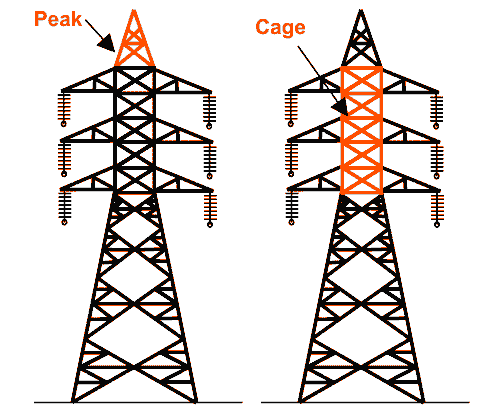
The main parts of these are shown in the pictures.
The peak of Transmission Tower
The portion above the top cross arm is called the peak of the transmission tower. Generally, earth shield wire connected to the tip of this peak.
Cross Arm of Transmission Tower
Cross arms of transmission tower hold the transmission conductor. The dimension of cross arm depends on the level of transmission voltage, configuration and minimum forming angle for stress distribution.
Cage of Transmission Tower
The portion between tower body and peak is known as cage of transmission tower. This portion of the tower holds the cross arms.
Transmission Tower Body
The portion from bottom cross arms up to the ground level is called transmission tower body. This portion of the tower plays a vital role for maintaining required ground clearance of the bottom conductor of the transmission line. 


Design of Transmission Tower

During design of transmission tower the following points to be considered in mind:-
a) The base ground leeway of the most minimal conductor point over the ground level.
b) The length of the encasing string.
c) The base leeway to be kept up among conductors and among conductor and tower.
d) The area of ground wire as for external most channels.
e) The mid range leeway required from contemplation of the dynamic conduct of conductor and helping insurance of the line.
To determine the actual transmission tower height by considering the above points, we have divided the total height of tower in four parts:-
1. Minimum permissible ground clearance (H1).
2. Maximum sag of the conductor (H2).
3. Vertical spacing between top and bottom conductors (H3).
4. Vertical clearance between ground wire and top conductor (H4).
Types of Transmission Tower
As indicated by various contemplation, there are various kinds of transmission towers. The transmission line goes according to accessible halls. Because of inaccessibility of most brief separation straight passage transmission line needs to go astray from its straight way when hindrance comes. In all out length of a long transmission line there might be a few deviation focuses.
According to the angle of deviation there are four types of transmission tower-
1. A – type tower – angle of deviation 0o to 2o.
2. B – type tower – angle of deviation 2o to 15o.
3. C – type tower – angle of deviation 15o to 30o.
4. D – type tower – angle of deviation 30o to 60o.
As per the force applied by the conductor on the cross arms, the transmission towers can be categorized in another way:-
1. Tangent suspension tower and it is generally A - type tower.
2. Angle tower or tension tower or sometime it is called section tower. All B, C and D types of transmission towers come under this category.
Apart from the above customized type of tower, the tower is designed to meet special usages listed below:-
These are called special type tower:-
1. River crossing tower
2. Railway/ Highway crossing tower
3. Transposition tower
Based on numbers of circuits carried by a transmission tower, it can be classified as :-
1. Single circuit tower
2. Double circuit tower
3. Multi circuit tower.
Comments