Substation and its Components
Sub-Station
It is a conversion point between transmission-level voltages (such as 138 kV) and distribution level voltages (such as 11 kV). A substation has one or more step down transformers and serves a regional area such as part of a city or neighborhood. They are connected to each other by a transmission ring circuit.
Equipment and its function
1). Lightening Arrestor
This is the first component in an electrical substation, and the principle capacity of these segments is to shield the segments of the substation from passing high voltage just as stops the amplitude and duration of the flow of current. The light arrestor segments are associated among the earth just as a line which mean parallel to the parts under resistance at the electrical substation.
 |
| Bushings and Lightning Arrestor |
These parts divert the flow of current to the ground and hence secure the framework's conductor just as protection from damage.
ThLightning Arrestor does not let the lightning to fall on the station. If some lightening occurs the arrestor pull the lightening and ground it to the earth. They are ground it to the earth. They are grounded to the earth so that it can pull the lightning to the ground. The Lightning Arrestor works with an angle of 30 and 45 making alone.
2). Capacitor Voltage Transformer
A Capacitor Voltage Transformer is a transformer used in the power system to step down the Extra High Voltage signals and provide low voltage signals for measurements or to operate a protective relay. In its most basic form, the device consists of three parts - two C across which the voltage signals are split, an inductive element used to tune the device to the supply frequency and a transformer used to isolate and a further step down the voltage for the instrumentation or protective relay. The device has at least four terminals, a high voltage terminal for connection to the high voltage signals, ground terminals and at least one set of secondary terminals for connection to the instrumentation or protective relay.
Capacitor Voltage Transformers are typically single-phase devices used for measuring voltages in excess of one hundred KV where the use of Voltage Transformer would be uneconomical. In the practice the first C, C1 is often replaced by a stack of Capacitor connected in series. This results in a large voltage drop across the stack of capacitor that replaced the first Capacitor and a comparatively small voltage drop across the second capacitor C2 and hence the secondary terminal.
In a practical transformer, errors are introduced because some current is drawn for the magnetization of the core and because of drops in primary and secondary windings due to leakage X and winding resistance. One can thus talk of the voltage error which is the amount by which the voltage is less than applied V1 and phase error which is the phase angle by which the reversed V2 vector is displaced from V1 vector.
| Capacitor-Voltage Transformer |
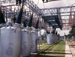
3). Power Transformer
The primary motivation behind the power transformer is to venture up the transmission voltage at the aging unit and venture down the transmission voltage at the circulation unit. For the most part for rating up to 10MVA (Mega-volt-Amperes) oil inundated, normally cooled and 3-stage transformers are utilized. So also, for more than 10MVA (Mega-volt-Amperes), air impact cooled transformers are utilized.
| Power Transformer |
Such sort of transformer worked at the full-load condition, and when it is at light burden condition then the transformer will be confined. Along these lines, the power transformer productivity can be most noteworthy at the full-load condition.
4). Instrument Transformer
They are used to step down the current or voltage to measurable values. They provide standardized, useable levels of currents or voltage in a variety of power monitoring and measurement application. The range of voltage and current are 110 V, and 1A (or) 5A. This transformer is also used for triggering the protective relay (AC type) by providing the current as well as voltage. These transformers are classified into two types namely a Voltage Transformer and a Current Transformer.
| Instrument Transformer |
Both Current Transformer and Potential Transformer are designed to have predictable characteristics on overloads. Proper operation of an overcurrent protection relay requires that current transformer provide a predictable transformation ratio even during a short circuit.
5). Current Transformer
They are basically used to take the reading of the current entering the substation. This transformer steps down the current from 800 Ampere to 1 Ampere. This is done because we have no instrument for measuring such a large current.
a). Distance protection
b). Back up protection
c). Measurement
| 33kV Current Transformer |
It is defined as an Instrument Transformer in which secondary current (under normal condition of operation. I2=I1 and differ in phase from it by an angle which is approved zero for an appropriate direction of the connection. This highlights an accuracy requirement of the current transformer but also important is the isolating function, which means no matter what the system's voltage secondary circuit need to be insulated only for low voltage.
The Current Transformer works on the principle of variable flux.
| Current Transformer |
In the ideal current transformer, I2 would be exactly equal (when multiplied by the turn ratio) and opposite to the I1 (I2=-I1). But as in the voltage transformer, some of the I1 or 1 A turns to be transformed into 2 A turns. This naturally introduces an error in the transformation. The error is classified into I2/I1 error
6) Potential Transformer
There are two potential used in the bus connected both sides of the bus. The potential transformer uses a bus isolator to protect itself. The main use of this transformer is to measure the voltage through the bus. This is done so as to get the detail information of the voltage passing through the bus to the instrument.
a). Measuring
b). Protection
The standard defines a voltage transformer as one in which the secondary voltage is substantially infinity to V1 and differs in phase from it by an angle which is approximately equal to zero for an approximate direction of the connection This in essence, means that voltage transformer has to be as close as possible to the ideal transformer.
In an ideal transformer, the V2 vector is exactly opposite and equal to the V1 (V2=-V1), when multiplied by the turns ratio.
| 25 kV Potential Transformer |
In a practical transformer, errors are introduced because some current is drawn for the magnetization of the core and because of drops in primary and secondary windings due to leakage X and winding resistance. One can thus talk of the voltage error which is the amount by which the voltage is less than applied V1 and phase error which is the phase angle by which the reversed V2 vector is displaced from V1 vector.
7). Busbar
The bus bar is a very important component in an electrical substation. It is a kind of current carrying conductor where many connections are made. In other terms, it can be defined as it is one type of electrical connection where the incoming current and outgoing current take place.
It is a line in which an incoming bus is used for putting incoming feeders in Lightening Arrestor single line. There may be a double line in the bus so that if any fault occurs in the one, others can still have current and supply will not stop. The two lines in the bus are separated by a little distance by a conductor having a connector between them. This is so that one can work at a time and other works only if the first is having any fault.
A busbar in electrical distribution refers to thick strips of Coppers or Aluminum that conduct electricity within a switchboard, distribution board, substation or other electrical apparatus.
The size of the bus is important in determining the maximum amount of current that can be safely carried. The bus bar is typically either flat efficiency due to their high surface area to cross-sectional area ratio. The skin effect makes 50-60 Hz. AC busbars more than about 8 mm (1/3 in thick) is inefficient, so hollow or flat shapes are prevalent in the higher current application.
 |
| Busbar |
A hollow section has a higher stiffness than a solid rod of equivalent current carrying capacity which allows a greater span between busbar supports in outdoor switchyards. A busbar may either be supported on an insulator or else insulation may completely surround it. The busbar is protected from accidental content either by a metal enclosure or by elevation out of normal reach.
Neutral busbars may also be insulated. Earth busbars are typically bolted directly onto any metal chassis of their enclosure. Busbars may be enclosed us a metal housing, in the form of bus duct or busway, segregated phase bus or isolated phase buses.
8). Circuit Breaker
This is a type of electrical switch, used to open or close the circuit when an error arises in the system. It includes two moving parts that are usually closed. When an error happens in the system, then the relay transmits the signal to the circuit breaker & therefore their parts are moved separately. Therefore, errors occur in the system turns into clear.
a). SF6 Circuit Breaker
The use of SF6 circuit breaker is mainly in the substation which is having high input kV, say above 220 kV and more. The gas is put inside circuit breakers by force i.e. under high pressure. The circuit breaker uses the SF6 gas to reduce the torque produced in it due to any fault in the line. The circuit breaker has a direct link with the instruments in the station when any fault occurs alarm bell rings.
 |
| 115 kV Siemen SF6 Circuit Breaker |
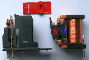
b). Spring Circuit Breaker
The spring type of circuit breaker is used for small kV stations. The spring here reduced the torque produced so that the breaker can function again. It is used for step down the side of 130kV to 33kV and 33kV to 11kV so on. They are only used in the low distribution sides.
 |
| Vaccum Circuit Breaker |
9) Wave Trapper
The wave-trapper is situated on approaching lines to trap the high-recurrence waves or unwanted waves. This flag (wave) originates from the remote station which intrudes on the current and voltage signals. This part trips the high-recurrence waves and diverts them to the telecom board.
 |
| Wave Trap |
Its shape is like a drum. It is connected to the main incoming feeder so that it can trap the waves which may be dangerous to the instruments in the substation.
10). Isolator in Substation
The isolator is one sort of electrical switch, used to isolate the circuit whenever the flow of current has been disrupted or extra voltage to the ground. Thus isolator is used after the bus for protection. These switches are named as disconnected switches, and it works under a no-load condition. Isolators are not inbuilt by an arc-quenching assembly, and they don't have a specific current-production or current-breaking limit. In certain circumstances, it is utilized to break the current charging of the line of transmission.
 |
| Electrical Isolator |
11) Control and Relay Panel
It Control and Relay panel is the most important equipment of the substation as it works as a shield guard for all substation equipment and electrical network. It is of cubical construction suitable for floor mounting.
All protective, indicating and control elements are mounted on the front panel for ease of O and C. The provision is made for terminating incoming cables at the bottom of the panels by providing a separate line up terminals blocks.
For cable entry, provision is made both from top and bottom. The control and relay panel accept CT, PT, AUX 230 AC and 220V/10VDC connection at respective designated terminal points. 220V/10V DC supply of all internal relays, timers and also for energizing closing and tripping coils of the beakers.
 |
| Control and Relay Panel |
Protective HRC fuse is provided within the panel for P.T. Each Capacitor bank is controlled by breakers and provided with line ammeter and selector switch for 3 phase system and overcurrent relay.
Under voltage and overvoltage relays, neutral current unbalanced relays are for both alarm and trip facilities breakers control switch with local/remote selector switch marks trip relay and trip alarm acknowledge and reset facilities.
12). Protective Relay
A protective relay is a relay device designed to trip a circuit breaker when the fault is detected. They are used to detect defected lines or apparatus to initiate the operation of circuit interrupting devices to isolate the defective equipment.
Relay is also used to detect abnormal or undesirable operating condition other than those caused by defecting equipment and either operate an alarm or initiate operation of the circuit interrupting devices.
Protection relay protects relays to protect the electrical system by causing the defective apparatus or lines to be disconnected to minimize damage and maintain service continuity to the rest of the system.
1). Overcurrent Relay
2). Distance Relay
3). Differential Relay
4). Directional Overcurrent Relay
 Substation Battery
 Switchyard
 Relay
Relay
 Capacitator Bank
1). Overcurrent Relay
2). Distance Relay
3). Differential Relay
4). Directional Overcurrent Relay
 |
| OverCurrent-Distance-Directional Protection Relay |
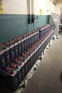
13). Batteries
In large power stations or substations, the operation of lighting, relay system, or control circuits are powered by batteries. These batteries are connected to a particular accumulator cell based on the operating voltage of the particular DC circuit.
Substation Battery
The batteries are classified into two types namely acid-alkaline as well as lead acid. Lead acid batteries are applicable for substations, power stations due to their high voltage & very economical low voltage.
14). Switchyard
The switchyard is the inter-connector among the transmission as well as generation, & equal voltage is maintained in this device. Switchyards are used to transmit the power which is generated from the substation at the preferred level of voltage to the near transmission line or power station.
Switchyard15). Relay
The relay is an electrical device, and the main role of this device in the substation is, it guards the grid component against the irregular conditions like faults. This is one type of detecting device, used to detect and determine the fault location, and then it sends the signal to the circuit breaker. After receiving the signal from the relay, the circuit breaker will detach the faulted part. Relays are mainly useful for protecting the devices from hazards, damages.
Relay16). Capacitor Bank
This device is inbuilt with capacitors that are connected either in series or else parallel. The main function of this is to store the electrical energy in electrical charge form. This bank draws primary current which amplifies the PF (power factor) of the system. As a source, the capacitor bank works for reactive-power, and the phase-difference among the current as well as the voltage will be decreased. They will enhance the capacity of ripple current of the power supply, and it removes the unnecessary characteristics within the system. The capacitor bank is an efficient method for preserving power factor as well as power-lag problem correction.
Capacitator Bank17). Carrier Current Apparatus
The carrier current apparatus is fixed in the substations for telemeter (Power Line Carrier Communication System), supervisory control (SCADA), relaying and communication. This system is correctly placed in a carrier room by connecting to the high-voltage power circuit.
18). Fire Fighting System
- Sensor or Detectors
- Water Sprays
- Fire port panels and Alarm System
- Water Tank and Spray System


Comments