Programmable Logic Controller
A programmable logic controller (PLC) or programmable controller is a solid-state/ computerized industrial computer that performs discrete or sequential logic in a factory environment. It was originally developed to replace mechanical relays, timers, counters. PLCs are used successfully to execute complicated control operations in a plant. Its purpose is to monitor crucial process parameters and adjust process operations accordingly. A sequence of instructions is programmed by the user to the PLC memory and when the program is executed, the controller operates a system to the correct operating specifications.
The first PLC system evolved from conventional computers in the late 60s and 70s. These first PLCs were installed primarily in automotive plants. Traditionally the auto plant had to be shut down for up to a month at model change over time. the early PLCs were used with other new automation techniques to shorten the changeover time. The PLC programming procedures replaced the rewiring a panel full of wires, relays, timers, counters and other components. The PLCs helped reduce the changeover time to a matter of few days.
Home Automation:- It is the delegation of the human control function to technical equipment for increasing productivity, better quality, increasing safety in the working condition and reducing manpower and cost.
Industrial Automation:- Products which makes under the control of computers and programmable controllers.
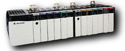 |
| Allen Bradley PLC |
Components used in Automation:-
1). Transducer
2). Transmitter
3). Control System
4). LEDs
1). Transducer:- Convert one form of energy into another such as mechanical forces into electrical form.
a). Heat, the intensity of light, flow rate, humidity, and pH valve are converted into an electrical signal.
b). Photoconductor converts light intensity into a change of resistance and thermocouple converts heat energy into electrical voltage.
c) Sensor:- It is a device that converts physical property such as temperature, pressure, humidity and flows, etc. into electrically or mechanically signals.
Widely used sensor:-
RTD:- Output in Ohm (Temperature)
Thermocouple:- Output in mV (Temperature)
Pressure Transmitter:- 4-20 mA. 0-10 V
Positional and Proximity Sensor:- Inductive, Capacitance, Ultrasonic, and Optical.
Flow and pH transmitter:- 4-20 mA, 0-10V
d). Actuator:- Convert electrical signals into physical properties. Eg:- Motors and Fans
2). Transmitter:- Output from a sensor or transducer may not be strong enough to be transmitted over a long distance. This device is used to amplify the signal or we say to convert the raw signal (experiment valve) into an electrical signal.
Analog PLC :- 3.75 mA --> noise occurrence , Voltage :- 0-10V, Current :- 4-20mA.
Digital PLC:- 12V DC --> noise occurrence, Voltage :- 24V DC
It is the largest trade association of electrical equipment manufacturers in the United States founded in 1926. It advocates for the industry and publishes standards for electrical products. Notably, the form of US household electrical outlets and plug is specified by NEMA.
3). Control System:-
a). PC-based control system.
b). PLC-based control system.
c). DCS-based control system.
d). PID Controller (Process Controller):- Proportional, Integral, and Derivature:- It provides the above three which help the unit to compensate automatically changes in the system.
PLC-based Control System
It is a solid-state/computerized industrial computer that performs discrete or sequential logic in the factory environment. Developed to replace relays, timers, and counters. It is used successfully to execute complicated control operations in a plant.
The first PLC modal 084 was invented by Dick Morley in 1969 and the first commercially successful PLC modal was introduced in 1973 and designed by Micheal Greenburg.
Application of PLCs
In an industrial set up PLCs are used to automate manufacturing and assembly processes. By process, we mean a step-by-step procedure whereby a product is manufactured and assembled. It is the responsibility of the product engineering dept. to plan for the manufacture of new or modified products. Other processes might involve the filling and capping of bottles, the printing of newspapers or the assembly of automobiles, etc.
Advantages of PLCs
- Reliability in operation.
- Flexibility in control techniques.
- Flexibility in programming and reprogramming in the plant.
- A large number of quantity of contacts.
- Online/Offline modifications.
- Cost-effective for controlling complex systems.
- Small physical size, shorter project time.
- In-house simulation & testing of the project.
- Speed in Operation.
- Ability to communicate with computer systems in the plant.
- Ease of maintenance/troubleshooting.
- Documentation.
- Security.
- The PLC is also designed to operate in an industrial environment with wide ranges of ambient temperature, vibration, and humidity and is not usually affected by the electrical noise that is inherent in most industrial locations. PC is often used for programming and monitoring the PLC.
Types of PLCs
1). Compact PLC (Fixed/Unitary):- Each & Everything assembles in a single unit such as Power System, Microprocessor, communication modulesv& CPO. It has fixed numbers of inputs and outputs.
2). Modular PLC (Extendable):- In it, we increase the number of inputs and outputs. The module is inserted into the slot and the slot is mounted on a base of PLC.
3). Rack Type PLC:- Modification of modular (DCS). It adds inputs and outputs outside of PLCs.
Architecture of a PLC
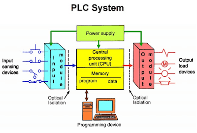
A Typical PLC can be divided into four components:-
- Processor Unit
- Power Supply
- Input/Output
- The Programming Device
Central Processing Unit
All processors are designed to carry out arithmetic and logic operations. Microprocessors are the brains of every computer, have a unique characteristic - they are programmable which means they are told what to do by the program. Microprocessors are classified mainly by two factors bit size and clock speed. There are 4,8, 16, 32, and 64-bit microprocessors, which manipulate data 4, 8, 16, 32, and 64-bit at a time respectively. A microprocessor is a part of a PLC CPU that receives, analyzes processes, and sends data.
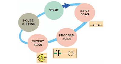
Four Steps in PLC scan cycle:-
Normally, before any output devices can be turned ON or OFF, the processor has to scan the entire program that is in user memory. The program may be only of a few rungs or it may be hundreds of pages in length, depending on the equipment that is being controlled.
1). Input Scan:- Detects the state of all input devices that are connected to the PLC.
2). Program Scan:- Executes the user-created program logic.
3). Output Scan:- Energizes or de-energies all output devices that are connected to the PLC.
4). Housekeeping:- This step includes communication with programming terminals, internal diagnostics, etc.
Programming Langauge used to Program a PLCs:-
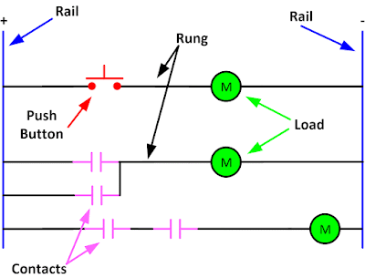
Ladder Logic is the most commonly used PLC programming language.
1). Ladder Diagram (LD):- Traditional ladder logic is a graphical programming language. Initially, programming with simple contacts that simulated the opening and closing of relays, Ladder Logic programming has been expanded to include such functions as counter, timers, shift, registers and math operations.
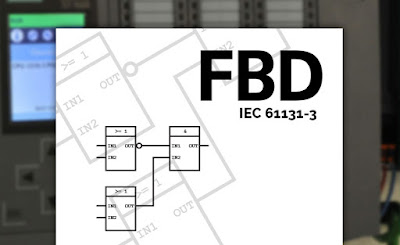
2). Function Block Diagram (FBD):- A graphical language for depicting signal and data flows through re-usable function blocks. FBD is very useful for expressing the interconnection of control system algorithms and logic.
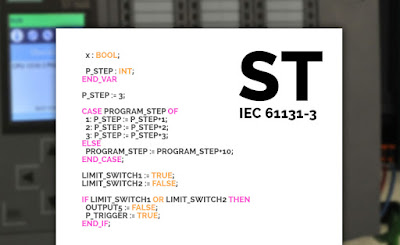
3). Structured Text (ST):- A high-level text language that encourages structured programming. It has a language structure (syntax) that strongly resembles PASCAL and supports a wide range of standard functions and operates. For examples:-
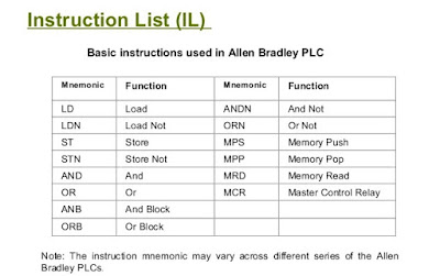
4). Instruction List (IL):- A low-level "assembler-like" language that is based on similar instructions list languages found in a wide range of today's PLC.
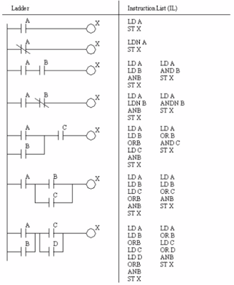 |
| Ladder Diagram vs Intruction List |
5). Sequential Function Chart (SFC):- A method of programming complex control systems at the more highly structured level. An SFC program is an overview of the control system, in which the basic building blocks are entire program files. Each program file is created using one of the complicated programming tasks into smaller, more manageable tasks.
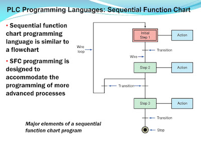 |
| Sequential Function Chart (SFC) |
Manufacturers of PLC:- Allen Bradley PLC’s brand is popularly referred to as AB PLC or Rockwell PLC brand. Both PLC brands provide diverse/extraordinary functions and capabilities. The ABB, AB, GE, Siemens, Delta, Mitsubishi, Honeywell, and Schneider are the other PLC brands extensively used, these days. Here are the extraordinary manufacturers of PLC with its beneficial software program for the compact PLC.
Memory Section
The processor memory consists of hundreds or thousands of locations that are referred as words. Each word is capable of storing binary data in the form of binary digits (1 or 0). The number of bits that a word can store will depend on the system of PLC. Words can be made up to 32 bits, 16 bits or 8 bits. the 16-bits word is the most common.
Types of Memory:-
The memory section of the processor consists of hundreds or thousands of locations where information is stored. It is divided into parts, user and storage.
- The user memory is for the storage of the user program, which contains the ladder logic, or instruction that controls the driven equipment.
- The storage memory is used to store information such as input/output status, timer or counters preset/accumulated values and internal control relays, etc. that are necessary for the processor to control the equipment.
- Volatile memory is one that loses its stored information when power is removed.
- Non-volatile memory has the ability to retain stored information when power is removed, accidentally or intentionally. Backup batteries included in the processor power supply protect volatile memory.
RAM (Random Access Memory):- Memories that have read and write capability. Since RAM is volatile, it must have a battery backup to retain or protect the stored program.
ROM (Read-only Memory):- A common non-volatile memory does not require battery backup & retains information or program when power is lost. Read-only indicates that the information stored in memory can be read-only and cannot be changed. Information in ROM is placed by the manufacturer does not want the information changed or altered.
EEPROM (Electrical Erasable Programmable Read-Only Memory) is also referred to as double EPROM (Electrical Programmable Read-Only Memory) and E2PROM. In EPROM program is erasable by ultraviolet rays and EEPROM is the chip that can be programmed by using a standard programmable device and can be erased by the proper electrical signal being applied to erase the pin. This is primarily used as a non-volatile backup for user program RAM.
- Get link
- X
- Other Apps
Labels:
Function Block Diagram
Industrial Automation
Instruction List
Ladder Diagram
PLC
Programmable Logic Controller
Sequence Function Chart
Structured Text
Location:
Noida, Uttar Pradesh, India
- Get link
- X
- Other Apps
Comments